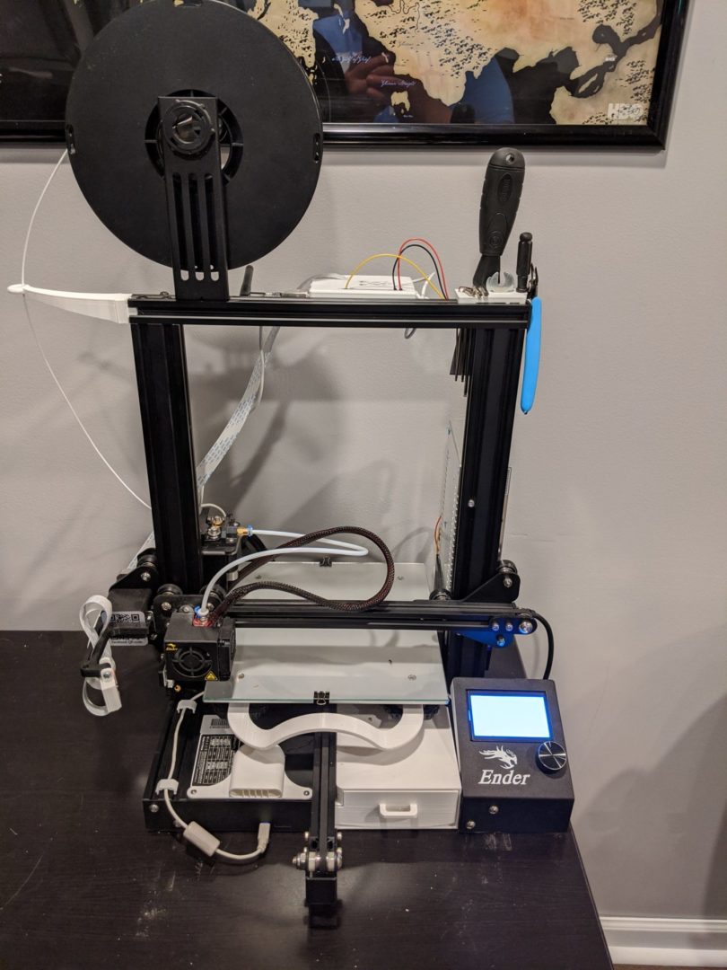
Back at it again! This round of upgrades have to do with remotely controlling power flowing to the printer. In previous posts I mentioned that I have my Raspberry Pi being fed power through the printers PSU. This is just to reduce how many outlets my printer needs (from 2 to 1). However, because its being fed from the PSU, right now its an all or nothing case when it comes to power. The Pi cannot run independently from the printer, which kind of sucks when it comes to remote use. This is the part where the Relay comes in!

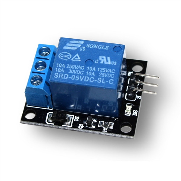
A Relay is essentially a fancy toggle switch. Part of the Relay allows high voltages/currents (10-15 Amps!!!). Its On/Off state is controlled by a low voltage controller, which gets its signals from the Raspberry Pi. Like I said, its a super fancy version of a light switch 🙂 Well lets get into the nitty gritty to how we’re gonna build this thing!

Planning for the Relay
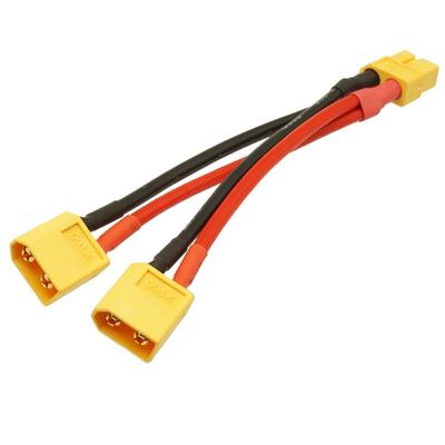
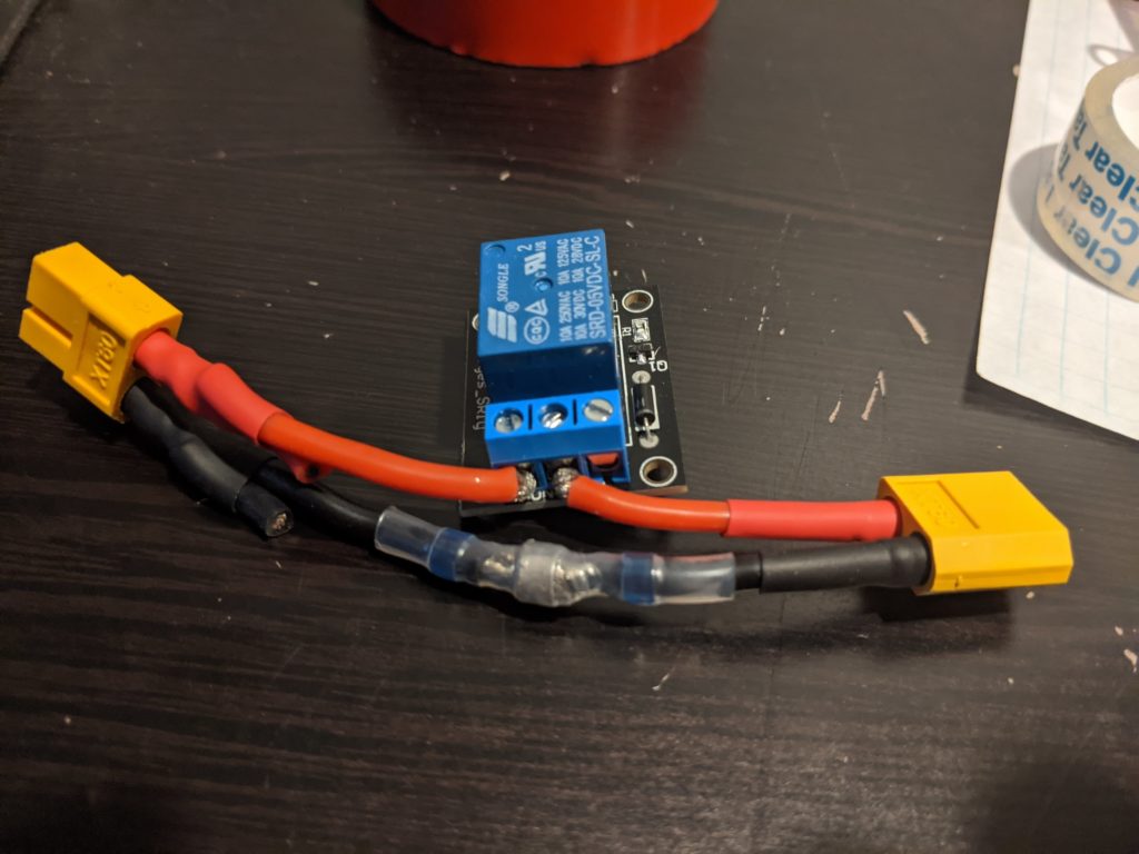
Regarding parts needed, I had all of the important ones on hand already. The only item I ordered was some quick soldering tubes. Not that I don’t trust my own soldering, but its 2020 and there are better/cleaner ways to solder now 🙂 I had an unused relay from a previous unfinished project, a spare Y connector from my Pi PSU siphon project, and plenty of wiring to go around.

So the 10,000 ft view of how things are going to go down:
- Rig up a dry run test, simple script to test the relay with a DMM
- Dry wire the PSU connection to the printer and test
- Build a printed case to enclose the relay
- Find a way to run Relay script from Octo-print
- Mount the case/relay, clean up wiring
- ????????????
- Profit
Relay Dry Run
The wiring test was probably the easiest step in this project. There are tons of other tinkerers out there that have done various projects using Pi’s and relays. The low voltage portion of the relay requires a 5V, ground, and signal pin from the Pi.
Finding the code was fairly easy.
import RPi.GPIO as GPIO
import sys

channel = [REDACTED]

GPIO.setmode(GPIO.BCM)
GPIO.setup(channel,GPIO.OUT)

def printer_on(pin):
        GPIO.output(pin, GPIO.HIGH)

def printer_off(pin):
        GPIO.output(pin, GPIO.LOW)

if __name__ == '__main__':
        if sys.argv[1] == 'ON':
                printer_on(channel)
        else:
                printer_off(channel)
This snippet assigns a GPIO pin on the Pi to push out a signal to the Relay. That signal toggles the high voltage, depending on the input parameter to the script. Calling the script directly from the terminal and hooking up the relay to a DMM to test conductivity, making it beep if there is a close circuit. Beeps were heard and the tests were successful!
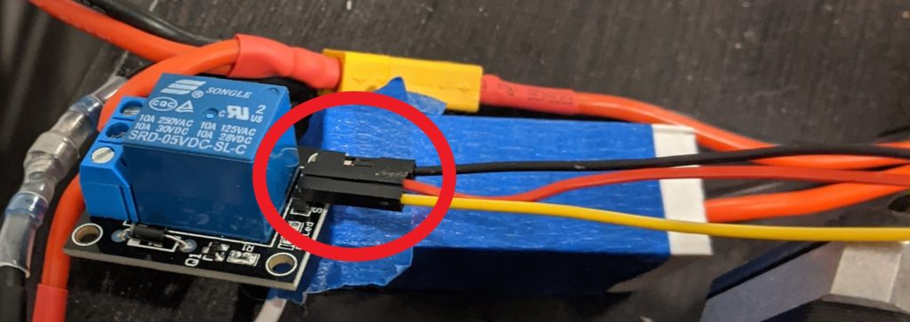
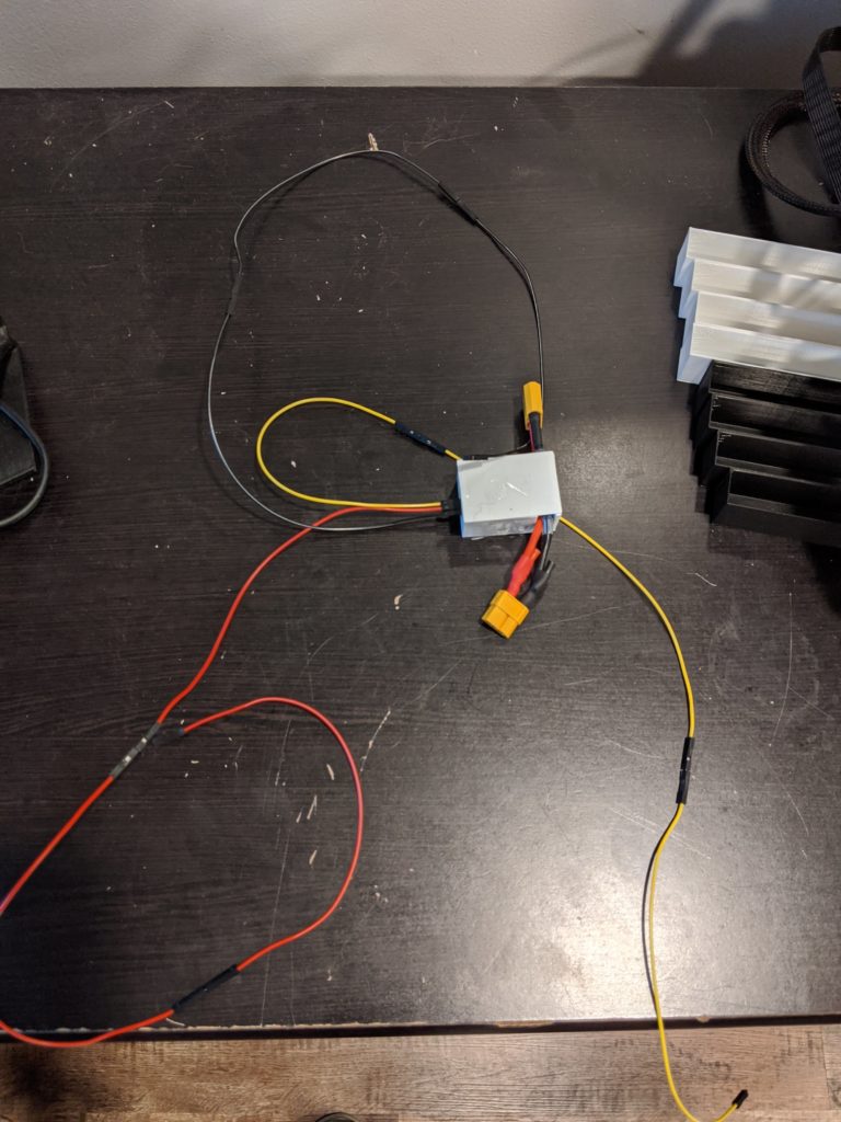
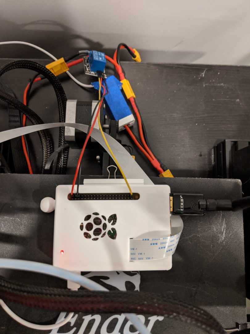
Building the Relay Case
With things tested out, the next thing on my list is to create an enclosure for the relay. Instead of going the route with my voltage regulator and pulling an enclosure from Thingiverse, I decided to make one from scratch. Using blender, I made a very poor attempt to construct one. Much of it had to do with my caliper being US SI, and everything software wise with 3D printing using metric, there were a few times some measurements got mistranslated. So after a few iterations, we get the end result!
Adding the Script to Octoprint
Doing a deep dive into the octoprint doco, there are a few places you can plug in custom scripts. Octoprint uses a master config YAML file. On boot, Octoprint parses out that YAML config and adds in the custom changes. Kind of like a docker file or a GitLab CI/CD config.
My original plan was to put a custom button that executes my python script. The button would sit in the controls tab along with all of the other printer GUI commands. On top of that, custom controls require a machine code, it doesn’t allow you to directly call python code via bash. There is a plugin that lets you put in custom commands that let you call in your python code. However, with the printer offline, Octoprint cannot connect to the printer. If it cannot connect, Octoprint just grays out all the buttons. So Plan B!
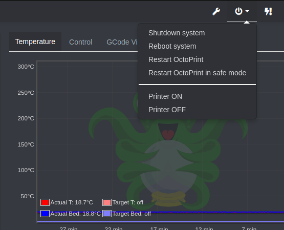
An alternate location in the YAML file would be through the system settings. System is the drop down at the top right of Octoprint, that controls if you want to reboot/shutdown Octoprint or the Pi. Also, no need for the custom command plugin. There is an action parameter that lets you call commands from bash directly. In the config I setup two entries, one for shutting the printer off and turning it back on. Here is the config entry:
system:
    actions:
    -   action: poweron
        command: python ~/scripts/power.py ON
        confirm: Turn ON Printer?
        name: Printer ON
    -   action: poweroff
        command: python ~/scripts/power.py OFF
        confirm: Turn OFF Printer?
        name: Printer OFF
Cleaning things up
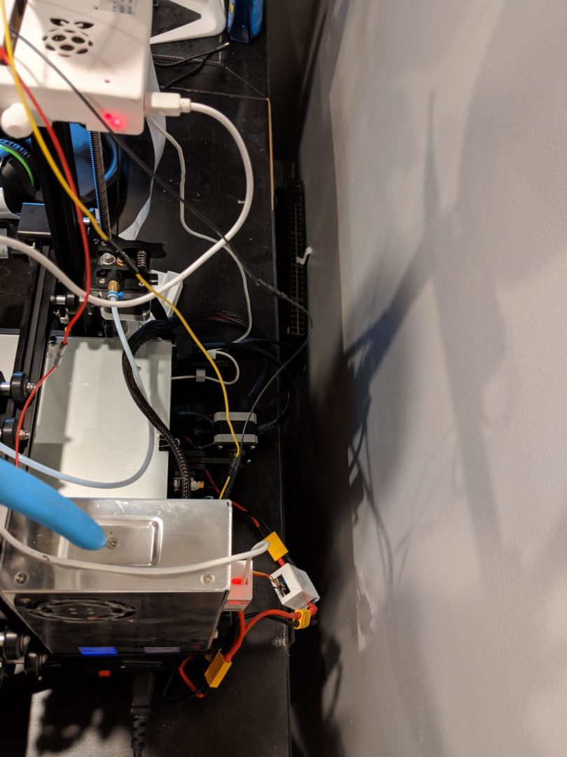
Functionality is all there, now its time to make it look presentable. Just like with the Voltage regulator, I mounted the relay to the back of the PSU just under the Volt Reg.
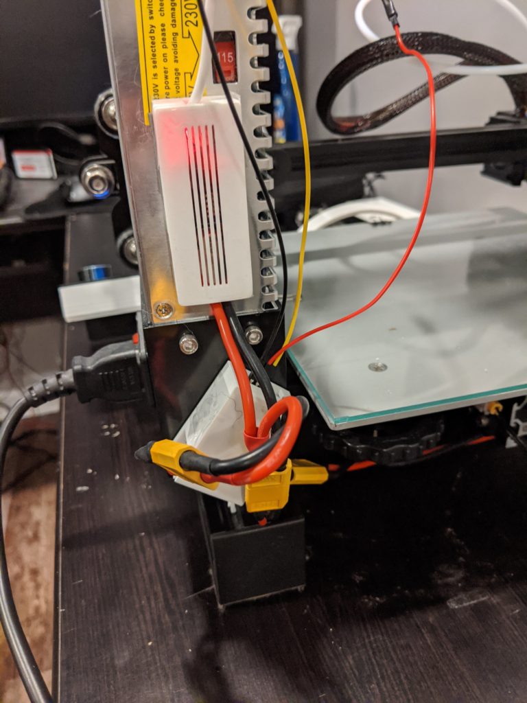
For the signal wires, I printed out some more cable clips to help keep them attached to the frame. Just a couple more shots of the construction of the relay setup and a video to showcase it all working.
So yep, that’s all I got this post! Next one might be about rigging up a cloud service that lets me access my printer fully remote. The current VPN setup I have isn’t the greatest and I’m hoping to find something that is super easy. Like Plex easy. Who knows! See ya next time!